Le TDP est un point de conception, pas une limite de puissance. Mesurez la dissipation réelle avant de dimensionner le dissipateur thermique. BQUQ (ISO9001, Dongguan) devis sous 12 heures.
TDP vs Puissance Mesurée : Pourquoi les Dissipateurs Thermiques sont Sous-Dimensionnés
Le TDP est une cible de conception, pas une limite de puissance mesurée, et le traiter comme la dissipation réelle est la raison pour laquelle les dissipateurs thermiques sont sous-dimensionnés : une puce évaluée à 65 W de TDP peut consommer 45 W en charge de travail moyenne, 88 W lors d'une brève rafale d'overclocking, et chaque fabricant définit ce chiffre différemment. Dimensionnez la solution thermique en fonction de la puissance soutenue mesurée dans le pire des cas, plus une marge — jamais uniquement sur la base de l'étiquette TDP.
Ces lettres signifient Thermal Design Power (puissance de conception thermique), et l'accent doit être mis sur « conception ». Le TDP indique ce que le système de refroidissement doit gérer pour que la puce fonctionne à sa fréquence nominale dans le cadre de la charge de travail de référence du fabricant — mais c'est le fabricant qui choisit la charge de travail, la température ambiante et le comportement d'overclocking. Votre produit exécute votre charge de travail dans votre boîtier à votre température ambiante, et le seul chiffre qui compte pour votre dissipateur thermique est la puissance que votre puce dissipe réellement dans votre pire scénario.
Ce que signifie réellement le TDP — et ce qu'il ne signifie pas
Les fabricants de puces utilisent le TDP comme spécification de refroidissement : la puissance que le refroidisseur de référence doit dissiper pour maintenir la puce dans sa limite thermique en fonctionnement nominal. Ce n'est pas la puissance électrique maximale que la puce peut consommer. Les processeurs modernes sont autorisés à dépasser temporairement le TDP via les mécanismes d'overclocking et de turbo, et certaines pièces de serveur exécutent des charges de travail soutenues au-dessus de leur TDP nominal lorsque les limites de puissance sont déverrouillées. Pour aggraver le problème, le « TDP » est interprété différemment selon les fabricants et même selon les gammes de produits d'un même fabricant.
| Étiquette que vous voyez | Ce que cela signifie généralement | Danger si utilisé comme puissance réelle |
|---|---|---|
| TDP (nominal) | Point de conception du refroidisseur de référence | Les rafales réelles dépassent ce niveau |
| Puissance d'overclocking/PL2 | Limite supérieure de courte durée (souvent 1,2–1,5× le TDP) | Les overclockings soutenus chauffent le dissipateur lentement |
| Puissance soutenue maximale mesurée | Votre charge de travail, votre carte, mesurée | C'est le chiffre à utiliser pour le refroidissement |
| Limite de puissance du package (PBP/MTP) | Configurable par le firmware | Peut être réglée au-dessus du TDP dans votre BIOS |
À retenir : lisez les petites lignes. Si la plateforme permet des états d'overclocking ou une limite de puissance déverrouillée, la cible de conception thermique est ce que le firmware autorisera réellement en continu — ce qui peut se situer 20 à 50 % au-dessus de l'étiquette TDP.
Pourquoi le sous-dimensionnement se produit dans les produits réels
Les dissipateurs sous-dimensionnés proviennent rarement de réductions de coûts malveillantes. Ils proviennent de trois erreurs honnêtes : utiliser le TDP comme puissance de conception, tester avec une charge de travail typique au lieu du pire cas, et tester à température ambiante au lieu de la température ambiante réelle du produit. Chaque erreur est mineure ; cumulées, elles expliquent comment un « refroidisseur de 65 W » se retrouve sur une carte qui consomme 88 W dans un boîtier à 45 °C.
| Entrée de conception | Hypothèse typique | Réalité sur le terrain |
|---|---|---|
| Chiffre de puissance | Étiquette TDP | Puissance soutenue maximale mesurée + excursions d'overclocking |
| Charge de travail | Benchmark du fabricant | Votre application, pire module, pires données |
| Température ambiante | Laboratoire à 25 °C | Boîtier à 40–60 °C, ensoleillement, altitude |
| Vieillissement du TIM | Pâte thermique fraîche | Dégradation de 2–5 °C sur des années |
| Flux d'air | Spécification ventilateur en air libre | Entrées restreintes, poussière de filtre, contre-pression |
À retenir : la solution n'est pas la paranoïa — c'est la discipline de la marge. La règle industrielle classique est de concevoir la solution thermique pour la puissance soutenue mesurée dans le pire des cas, puis d'ajouter une marge de 15 à 30 %, ce qui absorbe l'overclocking, le vieillissement et la dégradation du flux d'air en une seule fois au lieu de détailler chaque effet.
Un exemple réaliste : les chiffres derrière une puce « 65 W »
Prenons un processeur grand public évalué à 65 W de TDP. Dans une charge de bureau typique, il consomme 35–55 W. Sous une charge multi-cœurs intensive avec overclocking activé, il tire 88 W — 35 % au-dessus du TDP — par rafales de quelques dizaines de secondes à quelques minutes. Si le refroidisseur a été dimensionné pour 65 W sans marge, la rafale fait monter la température de jonction ; que cela ait de l'importance dépend du cycle de service, car la masse thermique du dissipateur absorbe les rafales courtes. Le mode de défaillance n'apparaît que lorsque la rafale est suffisamment longue ou que la charge de travail est soutenue : le dissipateur chauffe lentement, le ventilateur accélère, et la puce réduit sa fréquence au milieu du rendu de l'utilisateur.
| Condition de charge | Puissance typique de la puce | Ce que voit le dissipateur |
|---|---|---|
| Inactif/bureau léger | 15–35 W | Facile ; dissipateur proche de l'ambiante |
| Charge de travail typique soutenue | 40–60 W | État stable ; le dissipateur atteint l'équilibre |
| Rafale d'overclocking (secondes–minutes) | 80–100 W | Transitoire ; la masse thermique absorbe les rafales courtes |
| Pire cas soutenu (tous cœurs, déverrouillé) | 80–100 W+ | Le cas de conception — le dissipateur doit tenir ce niveau |
À retenir : les rafales courtes sont gérées par la masse thermique, pas par la surface des ailettes — un dissipateur à ailettes massives peut absorber un overclocking de 30 secondes avec seulement quelques degrés de variation. Le dissipateur doit être dimensionné pour le pire cas soutenu le plus long, et la courbe du ventilateur doit être réglée pour que le produit atteigne l'équilibre en dessous du point de limitation thermique, pas après.
Comment trouver le chiffre réel
Mesurez-le. Sur le banc d'essai, faites fonctionner le produit à charge maximale avec un wattmètre ou une pince ampèremétrique sur le rail d'alimentation du processeur tout en enregistrant la température, et laissez-le fonctionner assez longtemps pour atteindre l'équilibre — généralement 30 à 60 minutes, pas les 5 minutes que la plupart des tests de laboratoire utilisent. Répétez à la température ambiante la plus défavorable que le produit rencontrera, avec le boîtier fermé et l'entrée du ventilateur aussi restreinte qu'elle le sera sur le terrain. La puissance soutenue mesurée à ce moment est votre chiffre de conception. Si la mesure est impossible avant que la conception mécanique ne soit figée, utilisez le chiffre maximal soutenu du fabricant — la limite d'overclocking ou déverrouillée, pas le TDP — et appliquez la marge.
Spécifier le dissipateur avec le bon chiffre
Une fois la puissance réelle connue, le calcul de dimensionnement est le même que pour tout budget thermique : la résistance requise du dissipateur est égale à l'élévation de température autorisée divisée par la puissance mesurée, moins l'interface. Le guide de calcul de dimensionnement des dissipateurs thermiques présente l'exemple complet. Ce qui change avec la puissance mesurée, c'est la confiance : un dissipateur dimensionné à partir d'une puissance soutenue mesurée de 88 W avec 20 % de marge est une conception validée ; un dissipateur dimensionné à partir d'une étiquette de 65 W est un rapport de défaillance sur le terrain qui attend un été chaud. Pour le côté mécanique, le choix de construction suit la quantité et la géométrie comme toujours — dissipateurs thermiques extrudés pour les profils en volume, dissipateurs thermiques usinés CNC pour les faibles volumes ou les bases complexes — et la même règle s'applique à l'électronique de puissance, où les pertes des modules IGBT et SiC sont également sous-estimées par les valeurs typiques des fiches techniques ; notre guide de refroidissement des modules de puissance IGBT montre les chiffres côté module. Lorsque vous envoyez la demande de devis, incluez la puissance mesurée et la température ambiante, et l'usine pourra confirmer le dissipateur plutôt que de deviner.
Questions Fréquemment Posées
Q : Le TDP est-il identique à la consommation électrique maximale ?
R : Non. Le TDP est le point de conception du refroidissement que le fabricant spécifie pour une charge de travail de référence. Les puces réelles peuvent consommer moins en charge typique et plus pendant les rafales d'overclocking ou en fonctionnement soutenu déverrouillé — souvent 20 à 50 % au-dessus du TDP. Mesurez votre pire cas au lieu de vous fier à l'étiquette.
Q : Quelle marge dois-je ajouter au-dessus de la puissance mesurée pour un dissipateur thermique ?
R : Utilisez 15 à 30 % au-dessus de la puissance soutenue mesurée dans le pire des cas. Cette marge absorbe les excursions d'overclocking, le vieillissement du TIM, la poussière sur l'entrée du ventilateur et les variations de température ambiante sans avoir à détailler chaque effet. Les rafales courtes nécessitent moins de marge car la masse thermique du dissipateur les absorbe.
Q : Pourquoi mon processeur réduit-il sa fréquence alors que le refroidisseur est évalué au-dessus du TDP ?
R : Soit votre charge de travail maintient une puissance supérieure à la capacité du refroidisseur, soit la température ambiante est plus élevée que celle supposée par la spécification, soit le flux d'air est restreint par le boîtier. Enregistrez la puissance réelle et la température ensemble — le couple montrera quelle limite est atteinte et quand.
Q : Un dissipateur thermique plus grand aide-t-il avec les rafales de puissance courtes ?
R : Seulement jusqu'à un certain point. Les ailettes ajoutent de la surface pour le rejet de chaleur en régime permanent ; la masse thermique (principalement le métal de la base et des ailettes) absorbe les transitoires. Un dissipateur massif lisse les rafales courtes, mais une surcharge soutenue finira toujours par gagner — dimensionnez pour le cas soutenu et laissez la masse gérer les pics.
Q : Combien de temps doit durer un test thermique pour détecter un sous-dimensionnement ?
R : Assez longtemps pour atteindre l'équilibre à la charge du pire cas — généralement 30 à 60 minutes, parfois plus pour les grands dissipateurs passifs à forte masse thermique. Les tests courts manquent le réchauffement lent et renvoient des chiffres optimistes qui disparaissent sur le terrain lors d'un après-midi chaud.
Articles Connexes
- calcul-dimensionnement-dissipateur-thermique — Plus de la série technique d'ingénierie BQUQ Thermal Management.
- guide-refroidissement-module-puissance-igbt — Plus de la série technique d'ingénierie BQUQ Thermal Management.
- flux-travail-selection-dissipateur-thermique — Plus de la série technique d'ingénierie BQUQ Thermal Management.
Ressources Connexes
- À propos de BQUQ : une usine source certifiée ISO9001 à Dongguan exploitant quatre lignes de production sous un même toit.
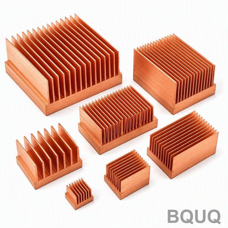
- Dissipateurs thermiques et pièces thermiques : options extrudées, usinées CNC et embouties de la ligne thermique — dissipateurs thermiques extrudés, dissipateurs thermiques usinés CNC, dissipateurs thermiques emboutis.
- Tendances industrielles : analyses de fabrication, de marché des matériaux et d'approvisionnement pour les acheteurs.
- Articles techniques : guides d'ingénierie et comparaisons de procédés — plus d'articles comme celui-ci.
- Centre FAQ : réponses rapides sur l'usinage CNC, l'emboutissage, les ressorts et les dissipateurs thermiques.
- Études de cas : pièces réelles et chiffres réels de projets que nous avons conçus et livrés.
- Contactez-nous : envoyez votre dessin et recevez un devis sous 12 heures ouvrables.
Rédigé par l'équipe d'ingénierie BQUQ. BQUQ est une usine source certifiée ISO9001 à Dongguan, en Chine, exploitant des lignes d'usinage CNC, d'emboutissage des métaux, de ressorts sur mesure, de dissipateurs thermiques et de pinces sous un même toit. Envoyez vos dessins à sc@bquq.com ou WhatsApp +86 13713157787 pour un devis sous 12 heures ouvrables. www.bquq.com