Choisissez un dissipateur thermique en 8 étapes, des watts et de la température ambiante à une référence pièce validée, avec des tableaux de décision. BQUQ (ISO9001, Dongguan) répond en 12 h.
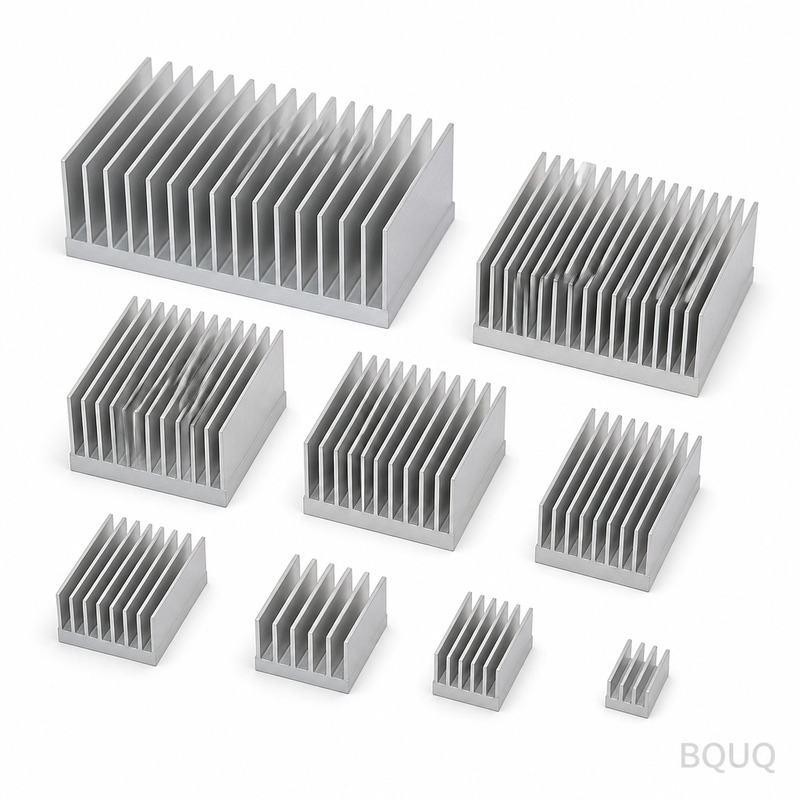
Sélection d'un dissipateur thermique en 8 étapes : des watts à la référence pièce
La sélection d'un dissipateur thermique est un entonnoir en huit étapes qui commence par les watts et se termine par une référence pièce : définir la puissance dissipée, fixer les limites de température, calculer la résistance thermique requise, choisir le mode de refroidissement, sélectionner le procédé de fabrication, dimensionner la géométrie, vérifier par mesure et valider avec les données d'inspection. Sauter la première étape — connaître réellement la puissance — est la cause la plus fréquente d'un mauvais choix de dissipateur.
Les ingénieurs ont tendance à se précipiter directement sur le catalogue, à la recherche d'un motif d'ailettes esthétique qui s'adapte à l'encombrement. Cela ne fonctionne que si le budget thermique a déjà été établi. Ce flux de travail impose d'abord le budget, puis le confronte à la réalité de fabrication des constructions extrudées, usinées CNC et embouties, et se termine par la vérification qui transforme une hypothèse en pièce validée.
Étapes 1–2 : Définir la puissance et les températures
L'étape 1 consiste à mesurer ou simuler la dissipation dans le pire cas — pas la valeur typique de la fiche technique ni la puissance marketing. Si le produit n'a pas été mesuré, construisez d'abord le prototype ou utilisez le chiffre maximal soutenu du fournisseur plus une marge ; notre guide TDP vs puissance mesurée montre à quel point les chiffres nominaux sous-estiment les pièces réelles. L'étape 2 fixe trois températures : la température maximale de jonction ou de boîtier issue de la fiche technique du composant, la température ambiante dans le pire cas sur toute la durée de vie du produit (y compris l'ensoleillement, l'altitude et les équipements voisins), et l'élévation de température cible qui préserve les marges de fiabilité.
| Entrée | Origine | Erreur courante |
|---|---|---|
| Puissance dissipée (W) | Mesure ou simulation du pire cas | Utiliser la valeur typique au lieu du maximum soutenu |
| Température max. de boîtier/jonction | Fiche technique du composant | Ignorer le déclassement à température ambiante élevée |
| Température ambiante du pire cas | Spécification produit + conditions terrain | Utiliser l'air de laboratoire à 25 °C pour un produit extérieur |
| Élévation de température autorisée | Objectif de fiabilité | Aucune marge pour le vieillissement du TIM ou la poussière |
À retenir : si l'une des quatre entrées est une hypothèse, étiquetez-la et ajoutez une marge à cette étape plutôt que de prétendre à une précision inexistante. Un budget basé sur une hypothèse de 10 W et une réalité de 18 W échoue sur le banc d'essai, pas dans le tableur.
Étapes 3–4 : Résistance requise et mode de refroidissement
L'étape 3 calcule le budget : la résistance requise dissipateur-air est égale à (Tboîtier,max − Tamb,max) / P moins la résistance d'interface. Les chiffres détaillés de cette étape figurent dans notre calcul de dimensionnement de dissipateur thermique. L'étape 4 décide du mode de refroidissement : convection naturelle, air forcé ou liquide. Le mode détermine toute la famille de géométries, et le choix est dicté par la densité de puissance et l'encombrement, pas par une préférence.
| Mode de refroidissement | Coefficient convectif typique | Enveloppe de puissance (typ.) | Exemples de produits |
|---|---|---|---|
| Convection naturelle | 5–14 W/m²·K (avec rayonnement) | Jusqu'à ~30–60 W avec de grands dissipateurs | Drivers LED, amplificateurs, alimentations passives |
| Air forcé, ventilateur axial | 15–60 W/m²·K | 30 W à plusieurs centaines de W | Ordinateurs, variateurs industriels |
| Air forcé, canalisé/soufflante | 40–150 W/m²·K | Haute densité, compact | Serveurs, télécom, empilements IGBT |
| Plaque froide liquide | 1 000–10 000 W/m²·K (vers fluide) | Flux très élevé | Onduleurs VE, diodes laser, HPC |
À retenir : choisir le mode tôt évite un travail inutile — personne ne devrait sélectionner le pas d'ailettes pour un dissipateur à convection naturelle quand le produit réel nécessite un ventilateur ou une plaque froide. Lorsque l'encombrement ne peut pas accueillir la solution passive, passez à l'air forcé avant de concevoir une géométrie d'ailettes héroïque.
Étapes 5–6 : Procédé de fabrication et géométrie
L'étape 5 fait correspondre la quantité et la géométrie à un procédé de fabrication. C'est là qu'une usine disposant de plusieurs lignes de production montre sa valeur, car le choix du procédé modifie à la fois le coût et la géométrie réalisable. L'étape 6 dimensionne ensuite le réseau d'ailettes réel — espacement, hauteur, épaisseur, épaisseur de la base — par rapport à l'objectif de résistance en utilisant les limites spécifiques au procédé.
| Situation | Procédé probablement le mieux adapté | Pourquoi |
|---|---|---|
| Profil standard adapté, quantité quelconque | Extrudé, coupé à longueur | Coût le plus bas, pas d'outillage si le profil existe |
| Profil personnalisé, 500+ pièces/an | Extrusion avec une nouvelle filière | Le coût de la filière est amorti ; meilleur coût par pièce |
| Petite quantité ou caractéristiques de base complexes | Usiné CNC à partir de matière pleine | Pas de coût de filière, planéité de base serrée et poches |
| Très grand volume, ailettes fines | Ailettes embouties ou pliées | Économie de tôlerie à partir de 100 000+ pièces |
| Densité extrême ou forme exotique | Ailettes rapportées ou décolletées | Géométrie que l'extrusion ne peut pas produire |
À retenir : la quantité décide du procédé plus que la performance. Un profil personnalisé de 50 pièces est coûteux car la filière est amortie sur 50 pièces ; le même profil à 5 000 pièces peut être l'option la moins chère de la carte. Pour des séries de moins de quelques centaines de pièces sans profil existant, l'usinage à partir de matière pleine est généralement la voie pragmatique — détails dans notre guide dissipateurs thermiques usinés CNC et les options de procédé sur nos pages dissipateurs thermiques extrudés et dissipateurs thermiques emboutis.
Étape 7 : Vérification par mesure
Chaque dissipateur sélectionné mérite une mesure avant validation. Montez le composant avec le matériau d'interface de production, alimentez-le à la puissance du pire cas dans la température ambiante du pire cas, et comparez la température de boîtier mesurée au budget. L'emplacement des thermocouples et la discipline d'essai sont importants ; notre guide test thermique des dissipateurs explique comment les essais sont réellement menés pour que le chiffre que vous lisez soit le chiffre vrai. Si la résistance mesurée est à environ 10 % de l'objectif, validez ; si elle ne l'atteint pas, le tableau de déclassement de l'article de dimensionnement vous indique quelle hypothèse réexaminer en premier.
Étape 8 : Validation avec les données d'inspection
La référence pièce n'est validée que lorsque le dessin, le procédé et la vérification concordent. Cela signifie un dessin avec la planéité de base et les caractéristiques de montage tolérées pour le matériau d'interface choisi, un procédé capable de maintenir ces caractéristiques, et un fournisseur qui expédie les données d'inspection avec le lot. Chez BQUQ, le dossier de validation est simple : une revue de dessin contrôlée ISO9001, un usinage selon les tolérances du plan, et des rapports d'inspection dimensionnelle avec chaque lot afin que la pièce approuvée sur l'échantillon soit celle qui se répète en production. Envoyez le dessin avec les watts, les températures, le flux d'air et l'encombrement à sc@bquq.com et le devis revient sous 12 heures ouvrables — les mêmes informations qui pilotent ce flux de travail sont tout ce dont une usine a besoin pour dimensionner et chiffrer correctement le dissipateur du premier coup.
Questions fréquemment posées
Q : Quelle est la première chose à savoir avant de sélectionner un dissipateur thermique ?
R : La puissance réellement dissipée dans le pire cas, mesurée ou simulée de manière prudente. Tout le reste — résistance requise, surface d'ailettes, choix du procédé — découle de la puissance, de la température ambiante et de la température maximale du composant. Les dissipateurs sont sélectionnés à rebours à partir d'un budget thermique, jamais en avant à partir d'une empreinte.
Q : Comment décider entre un dissipateur extrudé et un dissipateur usiné CNC ?
R : L'extrusion l'emporte lorsqu'un profil existant convient ou que le volume justifie une nouvelle filière (environ 500+ pièces par an) ; l'usinage CNC l'emporte pour les petites quantités, la planéité de base serrée, les poches, les bossages de montage ou les formes qu'aucune filière ne peut produire. La quantité et les caractéristiques géométriques décident, pas la préférence.
Q : Quel flux d'air dois-je prévoir si le produit n'a pas de ventilateur ?
R : Zéro. Utilisez la valeur en convection naturelle du dissipateur et espacez les ailettes de 6 à 10 mm pour que les couches limites ne se rejoignent pas. Ne sélectionnez jamais un dissipateur passif à partir de chiffres de catalogue en air forcé — la résistance en air calme peut être deux à trois fois plus élevée.
Q : Quelle marge thermique un design validé doit-il porter ?
R : Typiquement 15 à 30 % sur la puissance, plus un déclassement explicite pour l'altitude, l'orientation et l'obstruction du boîtier lorsque cela s'applique. La marge est peu coûteuse avant l'outillage et coûteuse après, donc la revue de validation doit vérifier la ligne de marge avant de vérifier le nombre d'ailettes.
Q : Quels documents doivent accompagner une commande de dissipateurs en production ?
R : Un dessin avec les caractéristiques de montage tolérées et la planéité de base, une spécification de matériau/alliage, la spécification de finition, et les rapports d'inspection dimensionnelle par lot. Pour les conceptions personnalisées, ajoutez le relevé d'essai thermique de l'échantillon afin que la performance fasse partie des preuves de validation, pas une hypothèse.
Articles connexes
- heat-sink-sizing-calculation — Plus de la série technique BQUQ sur la gestion thermique.
- heat-sink-thermal-testing — Plus de la série technique BQUQ sur la gestion thermique.
- heat-sink-cost-factors — Plus de la série technique BQUQ sur la gestion thermique.
Ressources connexes
- À propos de BQUQ : une usine source certifiée ISO9001 à Dongguan exploitant quatre lignes de production sous un même toit.
- Dissipateurs thermiques et pièces thermiques : options extrudées, usinées CNC et embouties de la ligne thermique — dissipateurs thermiques extrudés, dissipateurs thermiques usinés CNC, dissipateurs thermiques emboutis.
- Tendances industrielles : analyses de fabrication, de marché des matériaux et d'approvisionnement pour les acheteurs.
- Articles techniques : guides d'ingénierie et comparaisons de procédés — plus d'articles comme celui-ci.
- Centre FAQ : réponses rapides sur le CNC, l'emboutissage, les ressorts et les dissipateurs thermiques.
- Études de cas : pièces réelles et chiffres réels de projets que nous avons conçus et livrés.
- Contactez-nous : envoyez votre dessin et recevez un devis sous 12 heures ouvrables.
Rédigé par l'équipe d'ingénierie BQUQ. BQUQ est une usine source certifiée ISO9001 à Dongguan, en Chine, exploitant des lignes d'usinage CNC, d'emboutissage des métaux, de ressorts sur mesure, de dissipateurs thermiques et de pinces sous un même toit. Envoyez vos dessins à sc@bquq.com ou WhatsApp +86 13713157787 pour un devis sous 12 heures ouvrables. www.bquq.com